Category:KNX
Welcome to the KNX RF wiki! At this page we have collected everything concerning the KNX RF standard, such as development kit information, code examples and links to useful information. This wiki serves as a guide to implementing KNX RF products using MSP430F2/5 and CC1101 devices. It introduces KNX fundamentals and describes the software implementation that CAN be used to develop KNX products. In addition it gives detailed information on the CC-KNX-DK development kit. CC-KNX-DK is a small development system based on two Push-Buttons (called generic) and a dimmer actuator running on the SmartRF-TrxEB equipped with a high brightness white light LED board and a CC1101EM radio interface. The software is based on a fully certified KNX stack and associated applications. The KNX-standard configuration procedure without tools called Easy Mode is also embedded, but extended with an additional hager “Push Button System” to enhance the possibilities for the user. The KNX StandardThis section describes the KNX standard in brief terms and is based on the KNX handbook V2.0 from the KNX Association. KNX & KNX RF BasicsIntroduction to the KNX networkThis section outlines the main elements of the KNX system, and the concepts behind it. It is useful as a guideline for newcomers to the system, for product managers and development engineers looking for suitable implementation options within the system, as well as for those with experience from KNX “parent systems” to get acquainted with some new terminology and challenging new possibilities. Building Control technology as provided by KNX is a specialized form of automated process control, dedicated to the needs of home and building applications. One premise for KNX is to furnish a radically decentralized, distributed approach; hence the term network. The KNX Device Network results from the formal merger of 3 leading systems for Home and Building Automation (i.e. EIB, EHS and BatiBus) into the specification of the new KNX Association. The common specification of the “KNX” system provides, besides powerful runtime characteristics, an enhanced “toolkit” of services and mechanisms for network management. On the KNX Device Network, all the devices come to life to form distributed applications in the true sense of the word. Even on the level of the applications themselves, tight interaction is possible, wherever there is a need or benefit. All march to the beat of powerful Interworking models with standardized Datapoint Types and “Functional Block” objects, modelling logical device channels. The mainstay of S-mode (System mode) is the centralized free binding and parameterisation (typically with the PC-based ETS tool). It is joined by E-mode (Easy mode) device profiles, which can be configured according to a structured binding principle, through simple manipulations – without the need for a PC tool. These configuration modes share common run-time Interworking, allowing the creation of a comprehensive and multi-domain home and building communication system. The available Twisted Pair and Powerline communication media are completed with Radio Frequency (868 MHz band). KNX explicitly encompasses a methodology and PC tools for Project Engineering, i.e. for linking a series of individual devices into a functioning installation, and integrating different KNX media and configuration modes. This is embodied in the vendor-independent Engineering Tool Software (ETS) suites for Windows. In contrast to the “one size fits all” creed, the KNX system is entirely independent of any specific microprocessor platform or even architecture. Depending on the profile chosen by the manufacturer, one can select any suitable industry-standard chip, or opt for available KNX OEM solutions like Bus Coupling Units, BIM‟s, chip sets etc. Some KNX profiles allow a tiny system footprint (say < 5 kb), and easily run on an 8-bit processor. Other implementations use 16- or 32 bit processors, or even PC's in the full sense of the word. Through all of the above, KNX Device Networks may be flexibly adapted to present an optimal solution for each application domain and installation. Furthermore, they have also the capability to be inserted in a “Service Network” environment (usually based on broadband networks running IP, the Internet Protocol), to further amplify and leverage the benefits of our intelligent home, office or business environment. Joining all these requirements into one common, streamlined system – fulfilling stringent compatibility requirements with a large installed base – is no mean feat. The next section summarizes the essential bricks KNX uses to accomplish all this, while further sections zoom in more closely on some distinctive features and characteristics of the KNX system.  
KNX Components Overview
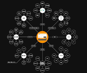
Elements of the KNX architectureKNX specifies many mechanisms and ingredients to bring the network into operation, while enabling manufacturers to choose the most adapted configuration for their market. The figure (knx_components.png) below shows an overview of the KNX model, bringing the emphasis on the various open choices. Rather than a formal protocol description, the following details the components or bricks that may be chosen to implement in the devices and other components a full operational system. As essential ingredients of KNX, we find in a rather top-down view. - Interworking and (Distributed) Application Models for the various tasks of Home and Building Automation; this is after all the main purpose of the system.
- Schemes for Configuration and Management, to properly manage all resources on the network, and to permit the logical linking or binding of parts of a distributed application, which run in different nodes. KNX structures these in a comprehensive set of Configuration Modes.
- A Communication System, with a set of physical communication media, a message protocol and corresponding models for the communication stack in each node; this Communication System has to support all network communication requirements for the Configuration and Management of an installation, as well as to host Distributed Applications on it. This is typified by the KNX Common Kernel.
- Concrete Device Models, summarized in Profiles for the effective realization and combination of the elements above when developing actual products or devices, which will be mounted and linked in an installation.
Applications, Interworking and BindingCentral to KNX application concepts is the idea of Datapoints: they represent the process and control variables in the system, as explained in the section Application Models. These Datapoints may be inputs, outputs, parameters, diagnostic data,…The standardized containers for these Datapoints are Group Objects and Interface Object Properties. The Communication System and Protocol are expected to offer a reduced instruction set to read and write (set and get) Datapoint values: any further application semantics is mapped to the data format and the bindings, making KNX primarily “data driven”. In order to achieve Interworking, the Datapoints have to implement Standardized Datapoint Types, themselves grouped into Functional Blocks. These Functional Blocks and Datapoint Types are related to applications fields, but some of them are of general use and named functions of common interest (such as date and time). Datapoints may be accessed through unicast or multicast mechanisms, which decouple communication and application aspects and permits a smooth integration between implementation alternatives. Network Management and ResourcesTo accommodate all active configuration needs of the system, and maintain unity in diversity, KNX is equipped with a powerful toolkit for network management. One can put these instruments to good use throughout the lifecycle of an installation: for initial set-up, for integration of multi-mode installations, for subsequent diagnostics and maintenance, as well as for later extension and reconfiguration. Network Management in KNX specifies a set of mechanisms to discover, set or retrieve configuration data actively via the network. It proposes Procedures (i.e. message sequences) to access values of the different network resources within the devices, as well as identifiers and formats for these resources – all of this in order to enable a proper Interworking of all KNX network devices. These resources may be addresses, communication parameters, application parameters, or complex sets of data like binding tables or even the entire executable application program. The network management basically makes use of the services offered by the application layer. Each device implementing a given configuration mode (see below) has to implement the services and resources specified in the relevant “profile” (set of specifications, see below). For managing the devices, these services are used within procedures. The different configuration modes make use of an identified set of procedures, which are described in the “configuration management” part. As indicated above, and further demonstrated in the Configuration Modes section below, KNX supports a broad spectrum of solutions here, ranging from centralized and semi centralised “master-slave” versions, over entirely peer-to-peer to strictly local configuration styles. However, mechanisms and Resources are not enough. Solid Network Management has to abide by a set of consistency rules, global ones as well as within and among profiles, and general Good Citizenship. For example, some of these rules govern the selection of the (numerical value of) the address when binding Datapoints. Communication: Physical LayersThe KNX system offers the choice for the manufacturers, depending on his market requirements and habits, to choose between several physical layers, or to combine them. With the availability of routers, and combined with the powerful Interworking, multi-media, and also multi-vendor configurations can be built. The different media are: - TP 1 (basic medium inherited from EIB) providing a solution for twisted pair cabling, using a SELV network and supply system. Main characteristics are: data and power transmission with one pair (devices with limited power consumption may be fed by the bus), and asynchronous character oriented data transfer and half duplex bi-directional communication. TP 1 transmission rate is 9600 bit/s. TP1 implements a CSMA/CA collision avoidance. All topologies may be used and mixed (line, star, tree, …)
- PL 110 (also inherited from EIB) enables communication over the mains supply network. Main characteristics are: spread frequency shift keying signalling, asynchronous transmission of data packets and half duplex bi-directional communication. PL 110 uses the central frequency 110 kHZ and has a data rate of 1200 bit/s. PL110 implements CSMA and is compliant to EN 50065-1 (in the frequency band without standard access medium protocol).
- RF Ready enables communication via radio signals in the 868,3 MHz band for Short Range Devices. Main characteristics are: Frequency Shift Keying, maximum duty cycle of 1%, 32768 cps, Manchester data encoding. The KNX RF stack described in this document applies to this.
- RF Multi enables communication via radio signals on multiple frequency in the 868,3 Hz band for Short Range Devices. It is compatible with RF ready.
Beyond these device network media, KNX has unified service- and integration solutions for IP-enabled media like Ethernet (IEEE 802.2), Bluetooth, WiFi/Wireless LAN (IEEE 802.11), “FireWire” (IEEE 1394) etc. Communication: Common Kernel and Message ProtocolThe Communication System must tend to the needs of the Application Models, Configuration and Network Management. On top of the Physical Layers and their particular Data Link Layer, a Common Kernel model is shared by all the devices of the KNX Network; in order to answer all requirements, it includes a 7 Layers OSI model compliant communication system. - Data Link Layer General, above Data Link Layer per medium, provides the medium access control and the logical link control.
- Network Layer provides a segment wise acknowledged telegram; it also controls the hop count of a frame. Network Layer is of interest mainly for nodes with routing functionality.
- Transport Layer (TL) enables 4 types communication relationship between communication points: one-to-many connectionless (multicast), one-to-all connectionless (broadcast), one-to-one connectionless, one-to-one connection-oriented. For freely bound models (see below), TL also separates (“indirects”) the network multicast address from the internal representation.
- Session and presentation Layers are empty.
- Application Layer offers a large “toolkit” variety of application services to the application process. These services are different depending on the type of communication used at transport layer. Services related to point-to-point communication and broadcast mainly serve to the network management, whereas services related to multicast are intended for runtime operation.
- KNX covers an extensive range of configuration and device models, the precise requirements governing a particular implementation are established in detailed Profiles, in line with the Configuration Modes. Within these boundaries, the KNX developer is encouraged to find the optimal solution to accommodate his implementation requirements! This is expounded in later sections. As we shall also find out later, the KNX message frame or telegram format also reflects this communication structure.
ResourcesWe have seen that Network Management consists of Procedures for manipulating Resources, and that the Common Kernel provides a toolkit of services for this purpose. Given central importance for the system, these Resources merit some further consideration. Remember that they can be: - “System” (configuration) resources, with address, lookup and parameter information to help the layers of the communication system carry out their task. By way of example, we mention the address and indirection tables for free Group Communication or the Individual Address of the node as such. Still among the system resources, we also find “discovery” information, which allows a partner on the network to find out about the capabilities of some other node or application. (One bonus of this is certainly that a very rich interaction becomes possible between Configuration Controllers or PC-based tools such as ETS, and the network.)
- Parameters controlling the application.
It is worth noting that KNX’ Interface Objects, provide a powerful, implementation-independent framework for realizing resources, the individual elements of which can be modelled as Datapoints. Device ModelsEventually, a KNX installation always consists of a set of devices connected to the bus or network. Every facet we have discussed so far is ultimately realized in and through the devices. All of these adhere to a number of logical node architectures for devices harbouring resources and implementing the protocol. Models vary according to node capabilities, management features and configuration modes; and not to forget, according to its role in the network, e.g. typical “application (end) device”, configuration master, router, gateway etc. KNX also standardizes certain general-purpose device models, such as for Bus Coupling Units (BCUs) or Bus Interface Modules (BIMs), mainly used in combination with ETS and downloadable application programs. Specifically for platforms like these, supplementary “hosting” API’s (2) are defined, such as the Communication Object model (see below), and the External Message Interface (EMI). Together with the characteristics of the Configuration Modes, these device models are all laid down in the Profiles. Device IdentificationIn complement to the basic operational system, a set of identification mechanisms is provided: - Devices may be identified and subsequently accessed throughout the network either by their individual address, their Domain Address, or by their unique serial number, depending on the configuration mode.
- Installation's extendibility and maintenance is considerably eased through product identification (i.e. a manufacturer specific reference) and functional identification (manufacturer independent) information retrievable from devices.
- Mechanisms are defined around the unique serial number feature to get individual address of a device with a given serial number (so providing further access) set individual address of a device with a given serial number retrieve serial number of a device at a given individual address
- The uniqueness of the serial numbers is ensured through controlled allocation of number ranges by the KNX Association Certification Department
System Capabilities, Communication and Addressing ModelsThe encoding space for addressing fixes some fundamental capabilities of the system in terms of size (maximum number of addressable devices and Datapoints). The addressing is reflected in the encoding format of the message frame or telegram, as is the “shadow” of the communication stack and kernel. Logical Topology and Individual Address SpaceKNX is a fully distributed network, which accommodates up to 65536 devices in a 16-bit Individual Address space. The logical topology or subnetwork structure allows 256 devices on one line. 2 lines may be grouped together with a main line into an area. An entire domain is formed by 15 areas together with a backbone line. Note that KNX KNXnet/IP optionally allows the integration of KNX subnetworks via IP. As shown in Figure 2, this topology is reflected in the numerical structure of the individual addresses, which (with few exceptions) uniquely identify each node on the network. On Powerline, nearby domains are logically separated with a 16-bit Domain Address. On RF, nearby domains are logically separated with a 48-bit Domain Address. Installation restrictions may depend on implementation (medium, transceiver types, power supply capacity) and environmental (electromagnetic noise, …) factors. Installation and product guidelines shall be taken into account. Couplers connect lines or segments, e.g. within the Twisted Pair (TP) medium, or different media; their functionality may be (some combination of) repeater, bridge, router, package filter (for traffic optimisation), firewall protection etc. KNX defines various standard coupler profiles. Network & Resource Management with Broadcast and Unicast “Point-to-point” ServicesTo manage network and device resources (e.g. when configuring an installation), KNX uses a combination of broadcast and point-to-point communication. Most often, each device in the installation is assigned a unique Individual Address via broadcast (optionally using a device’s unique serial number), which is used from then on for further point-to-point communication. A connection (optionally with access authorisation) may be built up, for example to download the complete ‘applet’ binary image of an application program. Some resources may also be accessed in connectionless point-to-point communication. Multicast “Group Addressing” for Run-time EfficiencyKNX supports full multicast (“group”) addressing, which provides the mainstay of KNX run-time communication. Full means that: - KNX is not limited to grouping devices: each device may publish several Datapoints (known as “(Group) Communication Objects”) individually, which can be grouped independently from one another into network-wide shared variables. As a bonus, properties of Interface Objects (see 4.3 "Properties of Interface Objects as Datapoints") may be published as shared variables as well.
- As explained above in the description of the group-oriented KNX communication stack, a shared variable can be fully read/write bi-directional. In this way, all devices can also send unsolicited multicast frames.
- KNX makes a 16 bit address space available for these shared variables. This signifies that one installation may have up to 64k shared variables (or “group addresses”), each with any number of local instances. In this way as well, KNX goes some distance towards reducing the need for redundant automation hierarchy levels (and bandwidth!) through appropriate addressing and device modelling schemes.
- On RF, KNX group addresses are extended by the serial number of the sender.
Frame OverviewNow’s the time to have a look at the actual KNX message format, as serially encoded in the frames or telegrams which are sent on the bus. Depending on the modulation technique or access and collision control of any specific medium, some preamble or envelope sequence may be defined, which we ignore here. The following example format actually corresponds to the interface above Layer2. Special acknowledge frames etc. are all described at length in the actual specification. 
KNX standard frame
First of all, the Control Field determines the frame Priority and distinguishes between the Standard and Extended Frame. In each case, there is an individual Source Address and individual (unicast) or group (multicast) Destination Address; the Destination Address type is determined by a special field.
A frame’s Hop Count is decremented by routers to avoid looping messages; when it becomes zero, the frame is discarded from the network. The TPCI controls the Transport Layer communication relationships, e.g. to build up and maintain a point-to-point connection. In turn, the APCI can tap into the full toolkit of Application Layer services (Read, Write, Response, …) which are available for the relevant addressing scheme and communication relationship. Depending on the addressing scheme and APCI, the standard frame can carry up to 14 octets of data. Segmentation for bulk transfer, like the download of an entire application program, is the responsibility of the management client, e.g. the ETS tool. Finally, the Frame Check helps ensure data consistency and reliable transmission. 
KNX RF frame
For RF, the standard frame structure (in gray), is just overlapped by RF serial number or domain address, and some additional fields to fit the FT3 data link layer (IEC870-5). Bit and octet orderData shall be transmitted most significant bit (MSB) fist. For data fields consisting of multiple octets (e.g. Serial Number and Device Addresses) the most significant octet (MSB) shall be transmitted first. Note that this convention is in line with other KNX media; however the metering protocol according to CEN TC294 transmits the LSB first. KNX RF ReadyThis chapter describes the RF physical layer requirements for KNX RF Ready. For KNX certification in Europe, the product shall be in compliance with the sections in this chapter. For KNX certification outside Europe and where the specific frequency is allowed, other physical parameters apply. KNX RF Ready Physical layerGeneral requirements for Physical Layer Type RF KNX Ready| Characteristic | Value or Applicable Standard | | TX Center Frequency | fc = 868,300 MHz | | Bandwidth | 600 kHz | | Max. TX Frequency Tolerance | ± 25 ppm (over temp, aging) | | TX Duty Cycle max | 1% | | TX Modulation Type | FSK | | FSK deviation | f_dev = ± 48 kHz to ± 80 kHz
Typically 60 kHz | | TX Chip Rate | 32 768 cps | | Maximum TX Chip Rate Tolerance | ± 1,5 % | | Maximum TX jitter per transition | ± 5 μs | | TX ERP | Typical : 0dBm
Min : -3dBm
Max: +14dBm | | Rx blocking performance | According to EN 300 220 1, category 2 receivers | | RX Center Frequency | fc = 868,300 MHz | | RX Frequency Tolerance | ± 25 ppm KNX TX to KNX RX
± 60 ppm Metering TX to KNX RX | | Minimal RX Chip Rate Tolerance | ±2,0 % | | RX Radiated SensitiVITY | Typical: -95 dBm
Minimal: -80 dBm | | Minimal operating temperature range | 0°C to 45°C |
KNX RF Ready systems datagram definition| Characteristic | Value | Notes | | Data encoding | Manchester | chip "0" means f_LO (= f_C - f_DEV)
chip "1" means f_HI (= f_C + f_DEV)
bit "0" is coded as f_HI to f_LO transition, chip sequence "10"
bit "1" is coded as f_LO to f_HI transition, chip sequence "01" | | Preheader | Consists of Preamble, Manchester violation, Sync word | See below | | Preamble | 79x chip sequence "01" sent by TX | Learning sequence for RX, number of preamble chips is not checked by RX (~4.8 ms) | | Manchester Violation | chip sequence "000111" | Necessary for capture effect | | Sync Word | chip sequence "011010010110" | Used for synchronisation on chip rate | | Postamble | 2 chips to 8 chips | Software reasons, mandatory for all TX, number of postamble not checked by RX. | | Capture effect | Optional | Preheader allows it; RX may use it |
Medium accessMedium access control serves for prevention of collisions on the medium RF. For two reasons medium access cannot be completely controlled on RF. - Unidirectional senders access the medium at non predictable times.
- Non KNX RF devices access the medium at non predictable times.
Bidirectional devices are able to sense whether the medium is free before they transmit. The interframe time is the time interval a bidirectional device waits for a free medium (regardless of whether it was addressed by the previous frame or not). If no preamble is detected during this interframe time the device may start sending. When a frame is received while the Physical Layer gets a request to send, the interframe time starts after the frame reception is completed, i.e. after the last CRC has been received. The same counts for sending: if the Physical Layer gets a send request while it is sending, the interframe time starts when the last CRC is transmitted. Note that RF supports no collision avoidance; therefore the transmission priorities are not coded in the message frame. Medium access times - Bidirectional devices interframe time: 15 ms
+ random delay: 0 ms to 15 ms - Retransmitters interframe time: 5 ms
+ random delay: 0 ms to 10 ms - Unidirectional devices time between datagrams: 150 ms
+ random delay: 0 ms to 10 ms The assumed typical ‘blind time’ for devices is 1 ms. The step for the random time is 1ms. KNX RF Data Link layerKNX RF Data Link Layer for all KNX RF devicesDifferences to existing (bidirectional) KNX protocolExtended Group AddressThe Extended Group Address (8 bytes) in a KNX RF frame shall be the combination of the standard KNX Group Address (2 bytes) with the KNX Serial Number of the sender of the frame (6 bytes). Every group addressed KNX RF frame shall contain an Extended Group Address. Any received frame shall be taken in account by the receiver only if the Extended Group Address of the sender is known by the receiver. Note that according to the RF frame, these 8 bytes are not transmitted consecutively. The RF frame shall contain the KNX Serial Number of the sender for the following communication modes: - point to multipoint, connectionless (multicast)
- point to system, connectionless (system broadcast).
This shall be indicated by the value 0 of the field AddrExtensionType in the second block of the RF frame. Multicast datagrams received with the wrong value of the AddrExtensionType shall be discarded by the receiving Data Link Layer instance. For other communication modes, the RF Domain Address shall be used. In any frame in system broadcast communication mode the Destination Address shall be 0000h and the Address Type shall be “group”. Predefined Extended Group Addresses for transmit-only devicesTransmit only devices shall use Extended Group Addresses. As transmit only devices only have sending Datapoints (only one Group Address per Datapoint), all addresses can and shall be factory set. For all unidirectional sensors, Datapoint 1 shall have Group Address = 0001h, Datapoint 2 shall have Group Address = 0002h, Datapoint N will have Group Address = N, with as result on the bus Extended Group Address (Serial Number of sensor, 0001h) , (Serial Number of sensor, 0002h) and (Serial Number of sensor, N). These Group Addresses shall be unique for each sender. All devices shall have the default Individual Address (05FFh). DD2 shall show the currently configured status of the channel. Please refer as well to Chapter 3/5/3 “Configuration Procedures”, clause 1.2 “Pre assigned Group Addresses in unidirectional devices”. In case generic channels are used, after sending the DD2, the transmit only device shall spontaneously send its parameters via A_NetworkParameter_Write PDUs (PID_Config_Link[Channel_Param_Response] ). This parameter block shall contain the currently configured state. Pre defined Extended Group Addresses for bidirectional devicesFor PB Mode, also the sending Datapoints of bidirectional devices shall use Extended Group Addresses that shall be composed in the same way: Device Serial Number, Group Object Number. This requirement does not hold for S Mode devices. The consequence from this is that groups consist of one sender and n receivers, hence form a 1 to n relationship. If several senders control a group of actuators, each of these actuators must listen to the sending addresses of all senders. RF Domain AddressThe RF Domain Address shall be a 6 byte number. The RF Domain Address in an RF installation shall always be identical to the KNX Serial Number of one of the devices in the installation. This guarantees that the RF Domain Address is a unique number. The RF frame shall contain the RF Domain Address for the following communication modes: - point to point, connectionless,
- point to point, connection oriented and
- point to all points, connectionless (broadcast).
This shall be indicated by the value 1 of the field AddrExtensionType in the second block of the RF frame. Point to point connectionless and point to point connection oriented datagrams received with the wrong value of the AddrExtensionType shall be discarded by the receiving Data Link Layer instance. For other communication modes, the KNX Serial Number shall be used. In any frame in broadcast communication mode the Destination Address shall be 0000h and the Address Type shall be “group”. RF Broadcast and RF System BroadcastBroadcasts can be broadcasts within an installation or system broadcasts. Whether a broadcast is a system broadcast shall be indicated by the AddrExtensionType field in the second block of the RF frame. - 0: system broadcast (shall not be restricted to the RF installation = domain; the frame shall contain the Serial Number of the sender).
- 1: broadcast (shall be restricted to the installation = domain; the frame shall contain the Domain Address).
Data Link Layer FrameGeneralThis clause specifies the frame format of the KNX-RF system. Note that no difference is made in coding Standard Datagrams and Extended Datagrams as on the other media. StructureThe frame format builds on the FT3 Data Link Layer (IEC 870 5). The frame consists of a preamble (Physical Layer), several data blocks, each followed by 2 bytes CRC, and a postamble (Physical Layer). The first data block has a fixed length of 10 data bytes. The following blocks contain 16 data bytes, except the last block, which may contain less than 16 bytes (the remainder). Note that the frame structure of extended datagrams is used, this is, there is no difference between standard and extended datagrams as on other media. The KNX Ctrl byte in the second data block contains the 4 bits “frame format”.
Overview of the Data Link Layer frame | 10 bytes | 2 bytes | 16 bytes | 2 bytes | | 2 bytes | | | Preamble | Data Block 1 | CRC | Data Block 2 | CRC | ... | CRC | Postamble |
Bit and byte orderData shall be transmitted most significant bit (MSB) first. For data fields consisting of multiple bytes (e.g. KNX Serial Number/Domain Address and Device Addresses) the most significant byte (MSB) shall be transmitted first. First block for Standard datagramsStructure of First Block| byte 1 | byte 2 | byte 3 | byte 4 | byte 5 to 10 | byte 11 and 12 | | Length | C | esc | RF info | SN/DoA | CRC | | | | 7 | 6 | 5 | 4 | 3 | 2 | 1 | 0 | | | | | | reserved | | | | RSSI | Battery State | Unidir | | | | 0x44 | 0xFF | 0 | | | | | | | | |
Description: According to IEC870-5: total number of user bytes counted from the C-field (excluding the CRCs). For media couplers, see § 6.1.6.4. Description: According to IEC870-5. KNX only uses SEND/NO REPLY (C = 44h) Description: This field shall have the fixed value FFh. Description: This bit is reserved and shall be set to 0. Description: This bit shall be set to 0 by the sender. See specific usage for bibat Description: These bits shall be set to 00b by the sender. Description: This field shall contain the received signal strength indication. This field shall be filled in by the Retransmitter with the lowest received signal strength, other senders shall always fill in the value 00h for this field. The Retransmitter shall not change the value if it cannot measure the signal strength. Encoding: 00b: void (no measurement) 01b: weak 10b: medium 11b: strong Description: This field shall contain the battery state of the sender of the frame. Encoding: 0: battery is weak 1: battery is ok Description: Unidir Encoding: 0: frame sent by bidirectional device 1: frame sent by unidirectional device Description: KNX Serial Number or Domain Address of the sender. The field AddrExtensionType in the LPCI in the second block shall indicate whether this field contains the KNX Serial Number or the Domain Address. Encoding MSB Description: CRC according to IEC870-5-1 Encoding: For information: The CRC according to FT3 of IEC 870-5-1 uses 216+213+212+211+210+28+26+25+22+20 as a generator polynomial. It starts with zero and treats the data msb first. The CRC result is complemented. The MSB of the 16-Bit CRC is transmitted first. Example: the sequence 01 02 03 04 05 06 07 08 has the CRC FCBC. Second block for Standard datagramsStructure of Second Block| byte 1 | byte 2 | byte 3 | byte 4 | byte 5 | byte 6 | | ctrl | Source Address | Destination Address | LPCI | | 7 | 6 | 5 | 4 | 3 | 2 | 1 | 0 | 7 | 6 | 5 | 4 | 3 | 2 | 1 | 0 | 7 | 6 | 5 | 4 | 3 | 2 | 1 | 0 | 7 | 6 | 5 | 4 | 3 | 2 | 1 | 0 | 7 | 6 | 5 | 4 | 3 | 2 | 1 | 0 | 7 | 6 | 5 | 4 | 3 | 2 | 1 | 0 | | f | f | f | f | EFF | EFF | EFF | EFF | | | | | | | | | | | | | | | | | | | | | | | | | | | | | | | | | AT | RC | RC | RC | LFN | LFN | LFN | AET |
| byte 7 | byte 8 | byte 9 to n | byte n+1 and n+2 | | | | | data | CRC | | 7 | 6 | 5 | 4 | 3 | 2 | 1 | 0 | 7 | 6 | 5 | 4 | 3 | 2 | 1 | 0 | 7 | 6 | 5 | 4 | 3 | 2 | 1 | 0 | 7 | 6 | 5 | 4 | 3 | 2 | 1 | 0 | | TPCI | TPCI | seq. num | seq. num | seq. num | seq. num | APCI | APCI | APCI | APCI | APCI/Data | APCI/Data | APCI/Data | APCI/Data | APCI/Data | APCI/Data | | | | | | | | | | | | | | | | |
Description: The frame format field is described in §6.1.3 - Extended Frame Format (EFF)
Description: The Extended Frame Format fiels shall specify the format of the frame. Encoding: 0000b = Standard Frame Other values shall be used for the LTE HEE Frame or are reserved. Description: The Source Address shall contain the Individual Address of the device that initiates the transmission of the frame. Description: This shall be the Destination Address of the frame and shall be an Individual Address or a Group Address. Description: This field shall specify whether the Destination Address is an Individual Address, a Group Address, an LTE Group Address the broadcast address or the broadcast address. Encoding: For the Standard Frame, the encoding shall be as follows:
0: Individual Address
1: Group Address Description Specifies the maximum number of repetitions allowed for one frame. - Data Link Layer Frame Number (LFN)
Description Sequence counter to discriminate successive frames. - Address Extension Type (AET)
Description: For the Standard Frame, the AET shall be used as follows: Encoding: 0: The field SN/DoA in the first block shall be interpreted as the KNX Serial Number of the sender. 1: The field SN/DoA in the first block shall be interpreted as the RF Domain Address. Description: The TPCI field shall contain the Transport Layer service indication.
00b: unnumbered data
01b: numbered data
10b: unnumbered control
11b: numbered control Description: This field shall contain the Sequence Number of the frame. Description: The APCI field shall contain the Application Layer service indication. Description: Up to 8 data bytes in this block (16 bytes max block length), subsequent data bytes in following blocks (each block 16 bytes, except the last block, which may contain less than 16 data bytes.) KNX CTRL field values| KNX ctrl bit | Frame type | | 7 | 6 | 5 | 4 | 3 | 2 | 1 | 0 | | 0 | 0 | 0 | 0 | e | e | e | e | Asynchronous Data Frames L_Data... | | 1 | 0 | 1 | 1 | r | r | r | r | Reserved | | 1 | 1 | 1 | 1 | 1 | 1 | 1 | 1 | Escape value for future KNX Ctrl Extensions (2 Byte KNX Ctrl FFxx) | eeee = EFF field, see data Link Layer spec.
r = reserved. Reserved or unknown coding of KNX Ctrl shall not be used by the transmitter and must be ignored by the receiver. |
Data Link Layer protocolAddrExtensionTypeThe AddrExtensionType bit shall be a parameter of the Data Link Layer instance. In transmission direction the sending Data Link Layer instance shall evaluate the AddExtensionType and set the correct data, either the devices own Serial Number or the Domain Address, in the field SN/DoA in block 1 of the transmitted frame. In reception direction the receiving Data Link Layer instance shall use this bit for a correct interpretation of the field SN/DoA in block 1 of the received frame as either Serial Number or Domain Address. This Data Link Layer parameter shall be set by the Application Layer and shall be passed through the communication stack by the other layers as input to the Data Link Layer. Duplication preventionGeneralIn the presence of retransmitters in the system, frame duplications can occur in the receivers if both the original sender and repetitions sent by the retransmitters are received. Therefore a mechanism is foreseen in Layer 2 to prevent the evaluation of duplicated datagrams in receivers. = Transmitters =The Data Link Layer of each transmitter shall insert a Link layer Frame Number (LFN) into the LPCI of each sent frame (see clause 3.9.1.2.5). The LFN shall be a 3 bit counter which shall be incremented for each transmitted frame. After 8 datagrams the counter wraps around and shall start off again from zero. In order to increase the probability to have no frame lost, the frame with the same LFN can be resent. = Receivers =The receiver shall discard subsequent datagrams, which contain the identical LFN from the same sender. In case the LFN differs, the newly received LFN shall be stored. Each receiver shall have a table to store the Serial Number and the LFN of previously received datagrams (no matter from where they are sent). The table length shall be less or equal to 8, because the LFN counts from 0 to 7. This avoids unintentional discarding of datagrams, even if datagrams from only one device are received. This mechanism ensures that repeated datagrams originating from the same sender up to within the following 8 datagrams are discarded. Data Link Layer servicesL_Data service and protocolIn addition to the general Data Link Layer protocol requirements specified in 0, for the L_Data-service, the following shall apply. The L_Data service on KNX RF shall either be an unconfirmed or a confirmed datagram service. If the local Data Link User prepares an LSDU for one or more remote Data Link Layer users, it shall apply the L_Data.req service to pass the LSDU to the local Data Link Layer. The local Data Link Layer shall accept the service request and shall try to send the LSDU to the remote Data Link Layer Users. The Destination Address may be an Individual Address, a Group Address or the Broadcast Address. The Local Data Link Layer shall pass an L_Data.con primitive to the Local Data Link Layer User that shall indicate a correct or erroneous data transfer. The Local Data Link Layer shall accept the L_Data.req service request. The fields SN/DoA, AT and AET shall be filled in as follows. If the service parameter address_type denotes an Individual Address then - the SN/DoA field in the frame shall be filled with the RF Domain Address;
- the Address Extension Type (AET) shall be set to 1; this shall indicate that the SN/DoA field shall be interpreted as the RF Domain Address
- the Address Type field shall be set to 0; this shall denote that the Destination Address shall be interpreted as an Individual Address.
If the address_type denotes a Group Address then - if the Destination Address value equals the broadcast address 0000h then
- the SN/DoA field in the frame shall be filled with the RF Domain Address;
- the Address Extension Type (AET) shall be set to 1; this shall indicate that the SN/DoA field shall be interpreted as the RF Domain Address
- the Address Type field shall be set to 1; this shall denote that the Destination Address shall be interpreted as a Group Address.
- if the Destination Address value does not equal the broadcast address 0000h but is a normal Group Address, then
- the SN/DoA field in the frame shall be filled with the KNX Serial Number of the sender;
- the Address Extension Type (AET) shall be set to 0; this shall indicate that the SN/DoA field shall be interpreted as the KNX Serial Number of the sender;
- the Address Type field shall be set to 1; this shall denote that the Destination Address shall be interpreted as a Group Address.
L_SystemBroadcast service and protocolThe Local Data Link Layer shall increment the Data Link Layer Frame Number (LFN) by one compared to the previous transmitted L_Data-frame. The Source Address shall be filled with the Individual Address of the Local Data Link Layer User. The Layer 2 of an RF RetransmitterHistory ListSenders shall set the LFN in the LPCI of each frame, as stated in clause 3.9.1.4.2.1.1. The Data Link Layer of every Retransmitter shall have a history list that shall store information about the previously received datagrams. The history list shall contain the Serial Number of the sender (not the Domain Addresses) and the LFN. When a Retransmitter receives a frame, its Data Link Layer shall check if the received Serial Number and LFN in this combination are contained in the history list. If this is the case, this frame shall be discarded, otherwise the processing shall continue. The history list shall have - A minimal length of 3 entries, and
- A maximum length of 7 entries or shall provide a deletion mechanism after a timeout (e.g. 3 s).
RF Repetition CounterIf the processing continues, the RF Repeater shall decrement the RF Repetition Counter and compare it with a limit value. If the processing continues, the RF Repetition Counter of the received frame shall be compared with a limit value. - If the received value of the RF Repetition Counter is larger than the limit value, then the RF Repetition Counter shall be decremented and the frame shall be repeated.
- If the received value of the RF Repetition Counter equals to or is smaller than the limit value, then the frame shall not be repeated and be ignored.
The limit value could optionally be a parameter into the RF Repeater to limit the number of RF Repeater levels. If implemented, this parameter shall be set or read using the property PID_RF_REPEAT_COUNTER (PID = 74) in the Device Object (object_type = 0). It shall be used by the RF Repeater in the following way: if rf_repetition_counter(rec_frame) > 0 and rf_repetition_counter(rec_frame) > rf_repetition_counter_limit(repeater) rf_repetetion_counter(rec_frame)--else discard(rec_frame)endifKNX RF Data Link Layer for KNX RF Ready systemsData Link Layer protocolData Link Layer for RF ReadyThe general KNX RF Data Link Layer requirements as specified in clause 3.9.1 ”KNX RF Data Link Layer for all KNX RF devices” shall apply. RF Repeat Counter for end devicesThe RF Repeat Counter shall be set to 6 for end devices. The Layer 2 of an RF RetransmitterFilteringFiltering not implemented in KNX RF Ready. KNX RF Ready Software StackThis section describes the software used to implement KNX devices. KNX RF Ready Stack ImplementationGeneral architecture
KNX RF Ready Stack Overview
The general architecture of the software in based on three layers: The Application layer deals with the user applications: - KNX channel implementation
- KNX RF comfort configuration
The application layer relies on the service of the communication layer. The communication layer deals with the KNX stack management. It proposes the services for communication with the media: - RF communication with the other RF products by the use of the KNX stack
The physical layer deals with all the physical peripherals used throughout the software in order to realize the interface with the physical devices: - Management of the specific microcontroller peripherals
- Analog to Digital converter
- Timers
- Digital control oscillator
- Interrupt
- Low power mode
- I/O pins management
- RF device management for the radio
The major point in the software architecture is that it is based on the usage of a scheduler, which manages tasks. All the major modules are represented by a task. The tasks are the following: A task communicates with another task by two ways: - Event (with data attached)
The principle is to trigger the tasks only when they have something to perform; that is only when they receive an event from another task or module. This mechanism of an event driven system is to allow the implementation of an efficient low power mode algorithm. This algorithm is in charge of determining the lowest current consumption mode according to the current actions. SchedulerThe Stack implementation is based on the scheduler. The scheduler performs: - All initialisations
- Waits a fixed init time before start the main loop.
- Main entry
- Run the task scheduler
- Run the time manager
- Run the LPM manager
Scheduler - Is implemented as a generic part independent of the microcontroller called in main function.
Time manager - Is implemented as a generic part independent of the microcontroller call by tick event
- Independent of the microcontroller:
- Calling of the Tempo management by interruption. Each event generates a tick.
- Optimisation of the tick value
- Determine the level of LPMI (In function of current tempo)
- Calling of the LPM manager to fix LMPI level
LPM Manager - Independent management of microcontroller LPM level (LPMI)
- Procedure proposition to fix LPMI level by service (managed by LPMI level request table).
- Synthesising of the LPMI level to determine the global LPMI level.
- Manage the microcontroller LPM with the LPMI level.
TasksThis section describes the different tasks present in the KNX RF Ready Stack. For a complete description of tasks and events please see the User's Guide. 
KNX RF Ready Stack Tasks
ammi_Man_Machine_Interface_TaskGeneral
These tasks manages the physical event coming from PMCO (Push Button) and interface these one with ACAT and APAT. Events
List of the AMMI events: - ammiCREATE_DELETE_LINK_EVT: Call CreateDeleteLinkEvt()
- ammiCONF_MODE_CHANGED_EVT: Call ConfModeChangedEvt()
- ammiPUSH_BUTTON_EVT: Call PushButtonEvt()
- ammiCHANNEL_UPDATE_EVT: Call ChannelUpdateEvt()
- ammiRFC_ERROR_LINK_EVT: Call RFCEndLinkErrorEvt()
- ammiRFC_END_LINK_EVT: Call RFCEndLinkOkEvt
- ammiRFC_OUTPUT_ACTUATOR_EVT: Call RFCOutputActuator()
AMMI Automaton Description This task manages the main automation “ConfigMode”: This one manage each mode of the product for RF Comfort (input/output), TX100 and ETS. The product have different operation mode and must be locked during each one (except CONFIG_FACTORY). These mode are enumerate in t_ConfigType: - CONFIG_FACTORY: for factory mode ( can be going in other mode)
- CONFIG_TX100: for TX100 configuration
- CONFIG_RF_COMFORT: for RF comfort configuration
- CONFIG_ETS: for ETS configuration
The product return to CONFIG_FACTORY mode after a factory configuration. acatConfigAppliTaskGeneral
This task manages the events of the RF comfort configuration coming through ammiManMachineInterfaceTask and apatProductAppliTask. The ACAT automaton is updated by the receiving of events and sends notification messages to ammiManMachineInterfaceTask. Events
List of scheduler tasks: - TASK_ID_CONFIG_APPLI: Call ConfigAppliTaskInit ()
- TASK_ID_CONFIG_APPLI: Call ConfigAppliTaskSave ()
- TASK_ID_CONFIG_APPLI: Call FifoEvent ()
List of the ACAT events received: - acatRxTelegramNotifyEvt: Call ConfigAppliTask_RxTelegramNotifytEvt ()
- acatConfigEvt: Call ConfigAppliTask_ConfigEvt ()
- TIMER_TIMEOUT_CONFIG: Call acatTimeoutConfig ()
- TIMER_TIMEOUT_CONFIG_TX100: Call acatTimeoutConfigTX100 ()
- TIMER_TIMEOUT_CONFIG_ETS: Call acatTimeoutConfigETS ()
- TIMER_TIMEOUT_RESPONSE: Call acatTimeoutResponse ()
List of the ACAT events sent: - ammiCONF_MODE_CHANGED_EVT: Call ConfModeChangedEvt ()
- ammiCREATE_DELETE_LINK_EVT: Call CreateDeleteLinkEvt ()
- ammiRFC_ERROR_LINK_EVT: Call RFCEndLinkErrorEvt ()
- ammiRFC_END_LINK_EVT: Call RFCEndLinkOkEvt ()
- ammiRFC_OUTPUT_ACTUATOR_EVT: Call RFCOutputActuator ()
- TIMER_DD2_SEND: Call apcoDD2Send ()
apatProductApplicationTaskGeneral**
This task manages the events of the RF comfort product coming through ammiManMachineInterfaceTask and drive to the channel Input/output. Events
List of scheduler tasks: - TASK_ID_PROD_APPL: Call ProductAppliTaskInit ()
- TASK_ID_PROD_APPL: Call ProductAppliTaskSave ()
- TASK_ID_PROD_APPL: Call FifoEvent ()
List of the APAT events received: - apatEndConfEvt: Call ProductAppliTask_EndConfEvt ()
- apatPushButtonEvt : Call ProductAppliTask_PBEvt ()
- apatRxTelegramNotifyEvt : Call ProductAppliTask_RxTelegramNotifytEvt()
- apatTimerEvt : Call ProductAppliTask_TimerEvt ()
List of the APAT events sent: - ammiCHANNEL_UPDATE_EVT : Call ChannelUpdateEvt ()
- acatRxTelegramNotifyEvt : Call ConfigAppliTask_RxTelegramNotifytEvt ()
Level 1: Task ckrtKnxRadioTaskGeneral
This task manages: - The layer Network, Transport and Application in reception of the KNX Stack.
- The layer Network, Transport and Application in transmission of the KNX Stack.
- The frame repetition in Network level (if the product is configured in repeater mode)
- The repetition of the object status in Application layer.
User Application Interface (by event)
Interface with the user application for the request of applicative property sending: - When the application user want to ask an sending application property, it call the procedure u_property_send() mapped on the property property_send() (in file csapp.c) in application layer.
- It must be add sending of the event skscTxPropertyRequestEvt in the procedure property_send().
- This event run the procedure ckalAppLayerTxUserProperty() by the scheduler to manage the asked applicative property (only if the asking was done by user).
Interface with user application for the request of applicative datapoint sending: - When the application user want to ask an sending application datapoint, it call the procedure u_datapoint_send() mapped on the property datapoint_send() (in file csapp.c) in application layer.
- It must be add sending of the event skscTxDatapointRequestEvt in the procedure datapoint_send().
- This event run the procedure ckalAppLayerTxUserDatapoint() by the scheduler to manage the asked applicative datapoints (only if the asking was done by user).
Events
List of scheduler entry points: - TASK_ID_SYSTEM_KNX: Call KnxRadioTaskInit ()
- TASK_ID_SYSTEM_KNX: Call KnxRadioTaskSave ()
- TASK_ID_SYSTEM_KNX: Call FifoEvent ()
List of the CKRT events received: - skscTxPropertyRequestEvt: Call KnxStackTask_TxPropertyRequestEvt ()
- skscTxDatapointRequestEvt: Call KnxStackTask_TxDatapointRequestEvt ()
- skscRxTelegramNotifyEvt: Call KnxStackTask_RxTelegramNotifyEvt ()
- skscTxTelegramRequestEvt: Call KnxStackTask_TxTelegramRequestEvt ()
List of the CKRT events sent: - ckptTxTelegramRequestEvt: Call KnxPhysicalTask_TxTelegramRequesttEvt ()
Level 0: Task ckptKnxPhysicalTaskGeneral
This task manages: - The physical repetition of the RF frame.
- The data layer reception of the stack KNX.
- Emission of physical frame RF.
- The data layer transmission of the stack KNX.
- The physical resources of the microcontroller for the LPM mode in function of the interruption.
Events
List of scheduler tasks: - TASK_ID_KNX_PHY_LAYER: Call KnxPhysicalTaskInit ()
- TASK_ID_KNX_PHY_LAYER: Call KnxPhysicalTaskSave ()
- TASK_ID_KNX_PHY_LAYER: Call FifoEvent ()
List of the CKRT events received: - ckptPermanentReceptionEvt: Call KnxPhysicalTask_ActivatePermanentReception()
- ckptAutoReceptionEvt: Call KnxPhysicalTask_ActivateAutoReception ()
- ckptTxTelegramRequestEvt: Call KnxPhysicalTask_TxTelegramRequestEvt ()
- TIMER_MEDIUM_BUSY_ID: ckptPostTimerMediaBusyNotifyEvt ()
List of the CKRT events sent: - ckrtRxTelegramNotifyEvt: Call KnxStackTask_RxTelegramNotifyEvt ()
Example ApplicationsThe KNX RF Ready stack IAR projects include two different Example Applications; - Dimmer Actuator
- Solar Powered Push Button
Configuration using Push-Button modeThis chapter describes the standard KNX push-button configuration procedure. In it also describes a special addition to the standard KNX Push Button procedure called Hager Push Button System. The KNX Push Button (and the Hager extension) is the only configuration option that is supported by the TI/Hager KNX Stack. Introduction to KNX Push ButtonIn the Push Button Mode (PB-Mode), no tool or external device (e.g. PC, Controller, ETS etc.) is needed for configuration and linking. The devices themselves do the setup of the links, the assignment of Individual Addresses and Group Addresses. To handle this, the devices support procedures for the configuration and the link management. To enable development and manufacturing of low cost products, the software overhead for the mandatory configuration and link procedures in the Push Button Mode devices must be as small as possible. A limited parameterisation is possible (local and over the bus: max size = two octets per parameter). The download of applications in PB-Mode is not possible. The applications must be pre-programmed or implemented statically. The term “push button” comes from the way to select the E-Mode Channels to link. Subunit: a set of Group Objects inside an E-Mode Channel. This is necessary in case of an E-Mode Channel with input - and output Group Objects with the same Connection Code (or compatible). There must be a possibility to select the input Subunit and the output Subunit. The best example is the CH_Logical_AND/OR. In PB-Mode there are two types of devices: - transmit-only, unidirectional devices, and
- bidirectional devices.
Hager Push Button SystemThe main goal of PBS specification is to enable simple configuration for simple automatisms, which expand the functionalities of the existing electrical installations. The Push Button System is invented by Hager and is primarily based on the standard KNX Push-Button configuration procedure. The Push-Button System protocol creates an additional layer above the KNX standard push-button procedure to make the configuration of devices easier for the installer. KNX productsProduct typesOnly bidirectional devices are in the scope of the Push Button System. This means that products must be bidirectional at least during the configuration procedure. LBT with input devices in runtimeThe unidirectional devices in runtime (but bidirectional in configuration) developed in accordance with the KNX RF Ready standard must be compliant with the following rules: - The devices developed in KNX RF Ready include a bidirectional RF radio chip
- Before a device transmits a command, the physical layer of the stack performs a check of the radio medium free by reading the current RSSI level and comparing it to a pre-defined RSSI threshold level.
- Only one frame is transmitted as the radio chip is a bidirectional chip (in KNX RF 1.1 and with really unidirectional radio chip, two frames were transmitted).
Sample of link procedureBy configuration, the user can use the input part of the On/Off device to control the load of a distant output device. In this case the device A is seen as an input device and the configuration is a classic push-button configuration between two separate devices. HardwareThis is a general description of KNX capable hardware from TI, for specific hardware in the CC-KNX-DK see the kit page. Supported Hardware PlatformsThe KNX RF Ready stack from TI is KNX certified to run on MSP430F2/5 with CC1101 as radio interface. Tools- SmartRF Packer Sniffer - The TI Packer Sniffer can be extended to support KNX RF. For instructions on how to setup the Packet sniffer have a look here. [TBA]
- KNX EITT - KNX EITT is a special analysis tool for KNX devices and installations. It is primarily used by manufacturers and test laboratories for testing, troubleshooting and monitoring the Interworking and system stack compliance of KNX products. EITT is also a powerful tool for the analysis and simulation of the KNX device network protocol. EITT can be used with the CC1111 USB dongle supplied in the CC-KNX-DK.
KNX CertificationScope of the KNX Certification Scheme for ProductsIn line with the KNX Association’s statutes, the purpose of the KNX Association’s Certification scheme for products is to: - Achieve a defined minimum degree of compatibility between products of different vendors (i.e. member companies of KNX Association).
- Establish the KNX trademark on a world-wide level as a token for quality.
- Increase the market success of the KNX technology in Home and Building Systems Engineering.
Owing to this Certification Scheme, the KNX logo signifies that: a) When used in connection with an application product: - The product complies with a product standard as chosen by the applicant as well as any (additional and/or higher) requirements of KNX Volume 4/1.
- The product complies with the minimum KNX system requirements for application products (see KNX Volume 6), including a defined minimum degree of interworking according to Volume 7 and functionality according to the manufacturer’s specifications.
b) When used in connection with KNX standardised basic and system components: - The product complies (if applicable) with the minimum KNX system requirements for basic and system components (see KNX Volume 6 respectively Volume 9).
- The product complies with the KNX hardware requirements as laid down in KNX Part 4/1.
- The product complies with the entire set of hardware interface requirements as laid down in Volume 9 (including the features marked as ‘standardised’).
Certification of productsIn order to establish the KNX Trademark as a token for quality and interoperability of home and building system engineering products (based on the KNX standard), KNX Association runs its certification scheme for products. RequirementsIf you, as a member of KNX Association wish to label a developed KNX product with the KNX trademark, shall prove compliance to the following requirements: - Quality system according to ISO 9001.
- European standard EN 50090-2-2 (covering such aspects as EMC, electrical safety, environmental conditions, of bus products) and an appropriate product standard. Compliance can be shown to KNX Association by the submission of a CE declaration.
- Volume 3 and Volume 6 of the KNX Specifications, the former being a toolbox of the KNX protocol features, the latter listing the allowed profiles of the KNX stack based on the toolbox as mentioned before.
- KNX Interworking requirements as regards standardised data types and (optionally) agreed functional blocks.
ProcedureFor registration (entry of the product data in the central database of the ETS software tool for project design and commissioning) and certification, the applicant will have to contact KNX Association’s Certification Department. In order to allow a speedy market entrance, products can be branded with the KNX trademark after Registration. After that, the applicant has a maximum of 6 months to complete the testing of his products. For software testing, the applicant has the choice of a number of KNX accredited test labs, authorised to carry out third party KNX system and interworking testing. For hardware testing, the applicant either has the various testing facilities at his premises or takes recourse to a test lab of his choice. During software testing, emphasis is put on testing of uncertified parts only. As an example, a product based on an already tested KNX bus access unit (of which compliance to the system specifications has already been proven) must merely be submitted to the interworking tests. A uniform test tool ensures that the manufacturer is able to prepare much of the software test campaign at his premises and provide this preparation as input for third party testing. As soon as KNX certification department has received all test reports as regards system and interworking conformity together with the CE declaration for the hardware, a certificate is issued confirming the use of the trademark on the tested product. Full information can be found in the KNX document “KNX certification of Products” and on KNX website. DocumentationLinks
 | Links | |
This category currently contains no pages or media.
| 


 提升卡
提升卡 置顶卡
置顶卡 沉默卡
沉默卡 喧嚣卡
喧嚣卡 变色卡
变色卡 千斤顶
千斤顶 显身卡
显身卡